Apollo quick start guide
This quick start guide is a quick walkthrough to set up an interface between MORAI SIM: Drive and an Apollo autonomous driving stack. It is intended to provide first-time users a chance to familiarize themselves with the different features of MORAI’s simulation environment. It will not provide in-depth explanations or how-to's for specific features and/or functions - please refer to the rest of the documentation for details.
This guide is written for Apollo 6.0 - newer versions of Apollo have since been released that may not be compatible with this guide.
Goals
This quick start guide will teach users to perform the following:
Correctly set up MORAI SIM: Drive to connect with Apollo
Conversely, correctly set up Apollo to connect with MORAI SIM: Drive
Run a simple routing maneuver
Perform obstacle avoidance maneuvers with lidar-based object detection
System configuration
The recommended system configuration for testing an Apollo system is a dual machine setup - one computer (PC #1) running MORAI SIM: Drive, with the other computer (PC #2) running Apollo. PC #1 can be either a Windows or Linux machine depending on user preference, as MORAI SIM: Drive is compatible with both. PC #2, on the other hand, is assumed to be operating Ubuntu 18.04.
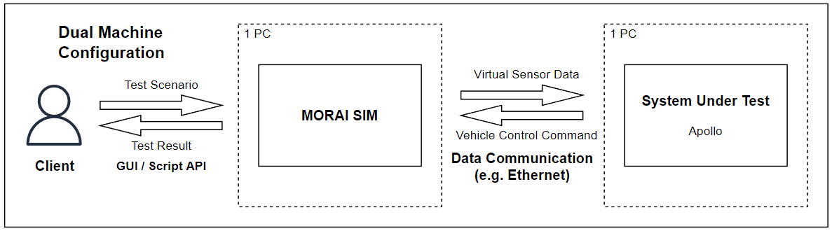
Though a single machine setup is possible, users will encounter performance issues in most cases, especially when using multiple sensor models.
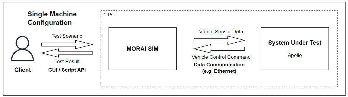
For more detailed information relating to system performance prerequisites, refer to this simulation machine requirements page and the Apollo prerequisites page.
Setting up MORAI SIM: Drive for Apollo
Starting MORAI SIM: Drive
For more details on installing and setting up MORAI SIM: Drive, follow this link.
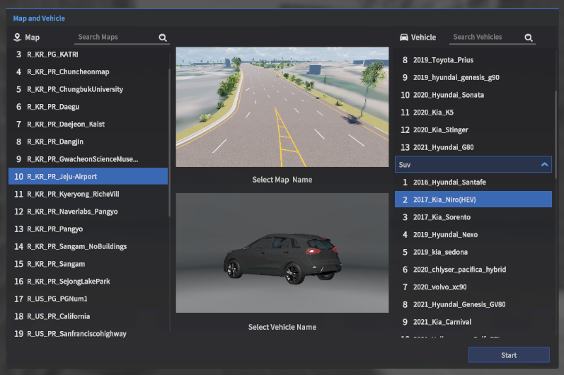
Selecting the test map and vehicle
Once the simulator finishes its initial loading process, choose the following from the Map and Vehicle selection screen.
Map:
R_KR_PR_Jeju-AirportVehicle:
2017_Kia_Niro(HEV)
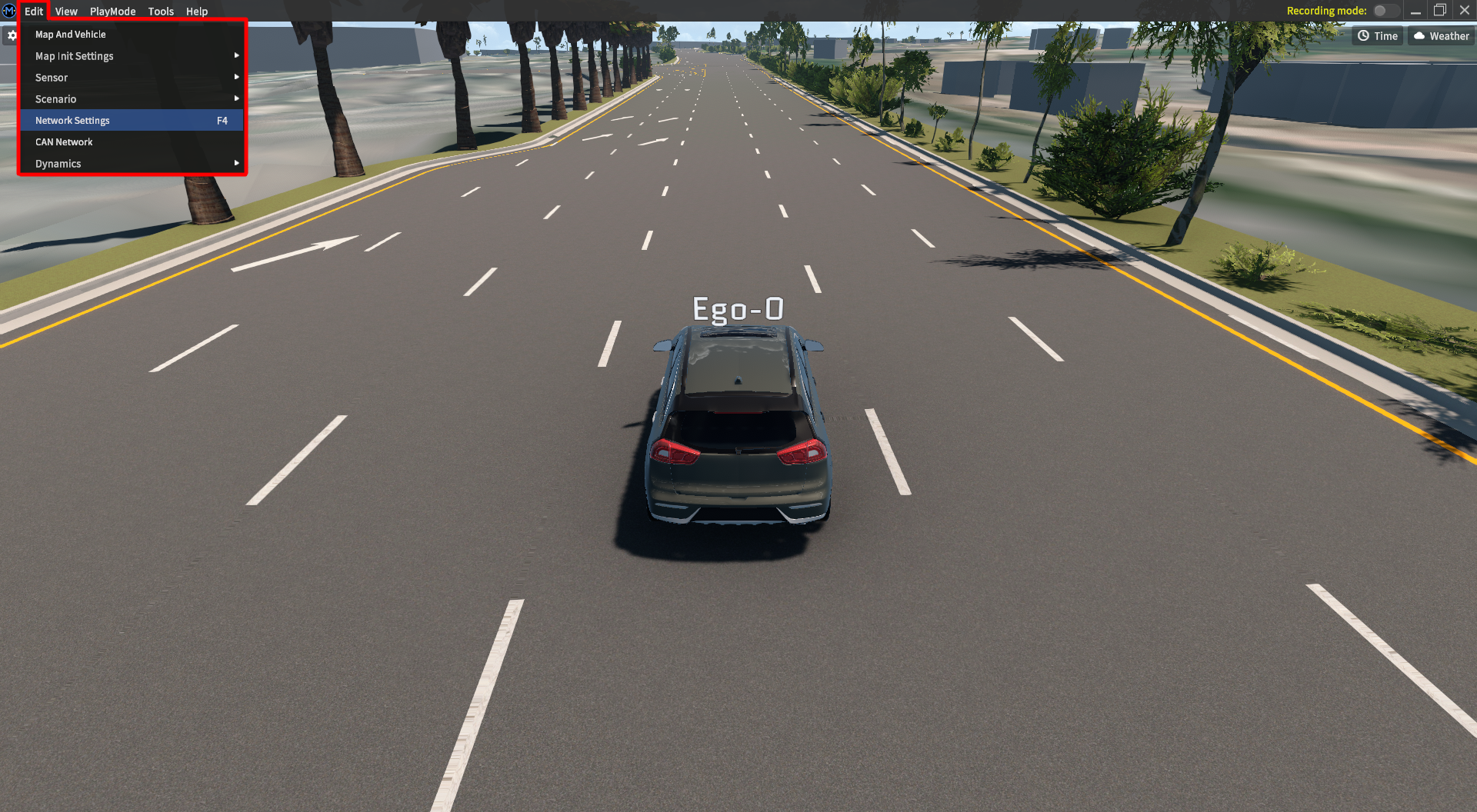
Configuring network settings to connect to Apollo
Open the Network Settings menu from the main menu bar. Go to Edit >> Network Settings.
To communicate with Apollo, the network module must be set to match the network settings of an Apollo Docker instance. Both the command/control interface and the publisher/subscriber/service interface must be configured, and are described in the next few subsections.
QUICK TIP As the simulator is not connected to any driver modules during this setup phase, it is recommended to manually set the vehicle to P (Parking) to ensure the ego-vehicle doesn’t creep off the road.
Cmd Control settings
Data transmitted from the system under test to MORAI SIM: Drive, which are typically command inputs, are managed from the Cmd Control tab. By default, the network is set to MoraiCmdController. Select the drop-down menu and choose CyberCmdController. The menu window should change to match the screen below.
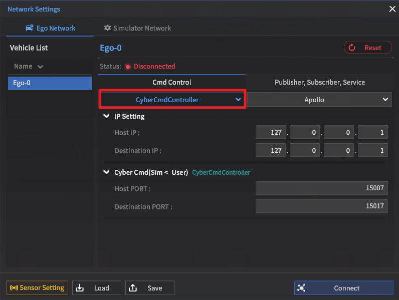
IP Setting
The Host IP is the IP address of the machine running MORAI SIM: Drive. The Destination IP is the IP address of the machine running Apollo.
If both MORAI SIM: Drive and Apollo are running on the same machine, all IP addresses should be set to 127.0.0.1.
QUICK TIP Check your systems' current IP with ipconfig for Windows and ifconfig for Linux.
Port number setting
The rest of the menu are fields for assigning port numbers for each of the connections required. These ports are set to a default value on startup, and do not need to be configured for the purposes of this guide.
As a reference, default port numbers are listed in a table.
Connection Name | Host | Destination | |
|---|---|---|---|
| 1 | CyberCmdController |
|
|
Publisher/Subscriber/Service settings
Data that originates from MORAI SIM: Drive, such as the vehicle state and sensor model output, is categorized under the Publisher, Subscriber, Service menu tab. The default network is set to UDP. Use the drop-down menu to set it to Apollo.
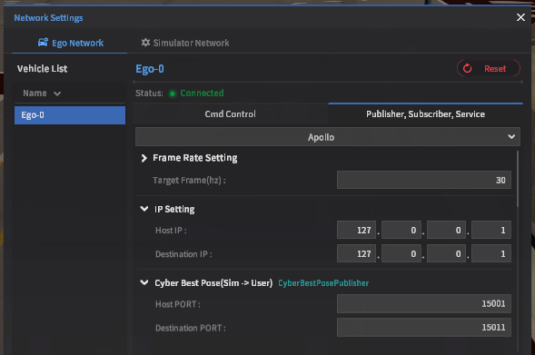
Frame Rate setting
The frame rate value is the target frequency at which data is sent from MORAI SIM: Drive to any connected system. As a target value, this frequency may not be met if performance issues with the host hardware exist.
For the purposes of this quick start guide, set the target frame rate to 30Hz.
IP Setting
IP addresses should match those set in the Cmd Control menu tab.
Port number setting
Port numbers are set to a default value on startup, and do not need to be configured for the purposes of this guide.
As a reference, default port numbers are listed in the following table.
Connection Name | Host | Destination | |
|---|---|---|---|
| 1 | CyberBestPosePublisher |
|
|
| 2 | CyberChassisPublisher |
|
|
| 3 | CyberCorrectedImuPublisher |
|
|
| 4 | CyberImuPublisher |
|
|
| 5 | CyberInsStatPublisher |
|
|
| 6 | CyberOdometryPublisher |
|
|
| 7 | MoraiObjectInfoPublisher |
|
|
| 8 | TLStatusPublisher |
|
|
Finalizing network settings
Once all the network setting values are set, press the Connect button on the bottom-right of the window. The status indicator should turn green and say Connected. The Connect button will turn red and change to Disconnect.
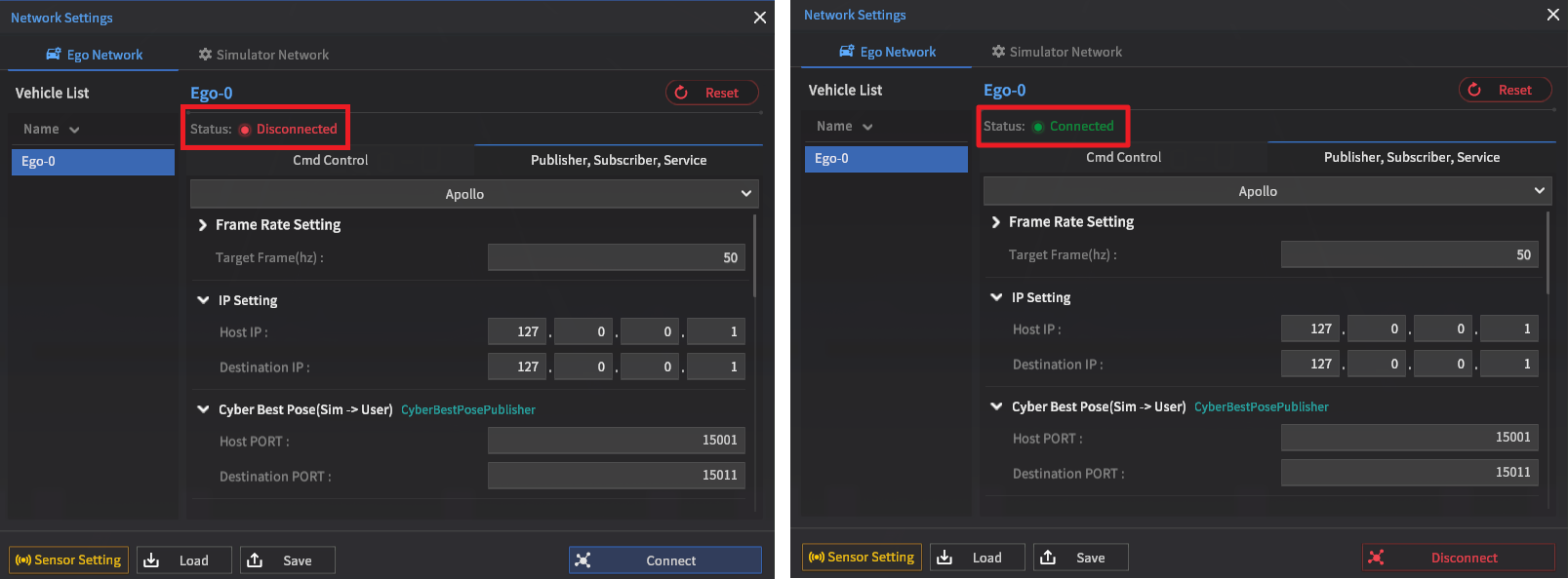
MORAI SIM: Drive is now ready to connect to an Apollo system. In this state, MORAI SIM: Drive will continuously broadcast the simulator’s state values and will immediately start to communicate once the CyberRT bridge begins running on the Apollo system.
Setting up Apollo for MORAI SIM: Drive
A quick intro to Apollo
Apollo is an open-source autonomous vehicle software platform developed by Baidu. It provides a wide range of technology support such as simulation, HD map planning, and vehicle module control.
Helpful links
System environment setup
Apollo requires a video graphics driver to function. As this may not be set up by default in a Linux installation, perform a quick check using nvidia-smi in the terminal. The terminal should return data similar to the following screenshot.
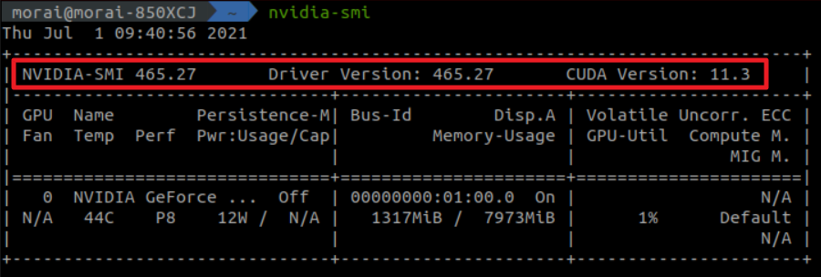
This guide was tested for NVIDIA driver version 465.27.
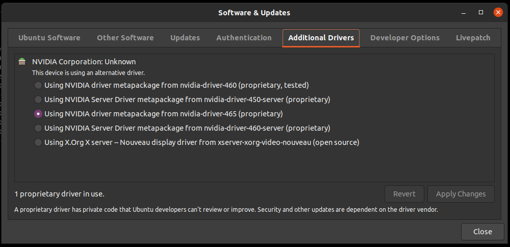
Performing a clean install
Should there be an issue with the NVIDIA drivers or if the system is completely new, graphics drivers can be installed with Ubuntu’s Software & Updates menu.
Once activated, move to the Additional Drivers tab and select an available NVIDIA driver metapackage. Click Apply Changes to begin installation.
Cloning the Apollo repository
Clone this forked repository of Apollo provided by MORAI - this fork was taken from the 21.12.08 MASTER branch of Apollo but adds modifications, such as a bridge for communicating with MORAI SIM: Drive.
IMPORTANT Please note that this guide will not work with an official release of Apollo as the necessary additional bridge code is not included in the official Apollo Github.
For users of MORAI SIM: Drive version 22.R2.1, clone the MORAISIM_R2.1 branch of the forked repository.
The MORAISIM_R2.1 branch fixes an error that occurs when connecting the Apollo fork to MORAI SIM: Drive version 22.R2.1
Installing Docker
Once the repository is cloned, run the install_docker.sh script to install Docker.
cd /apollo/docker/setup_host
chmod +x install_docker.sh

./install_docker.sh

sudo groupadd docker
sudo usermod -aG docker $USEROnce Docker is installed, install the NVIDIA Container Toolkit using the following shell script.
distribution=$(./etc/os-release;echo $ID$VERSION_ID)
curl -s -L https://nvidia.github.io/nvidia-docker/gpgkey | sudo apt-key add -
curl -s -L https://nvidia.github.io/nvidia-docker/$distribution/nvidia-docker.list | sudo tee /etc/apt/sources.list.d/nvidia-docker.list
sudo apt-get -y update
sudo apt-get install -y nvidia-docker2
sudo systemctl restart dockerFinally, reboot the system to finish installing.
sudo rebootStarting the Apollo Docker image
From the $APOLLO_ROOT_DIR directory, run the following shell script to enter the newly installed Apollo Docker.
./docker/scripts/dev_start.sh
./docker/scripts/dev_into.shA wired (not wifi!) internet connection is required to run the dev_start.sh shell file.
Getting ready to build
Before building Apollo, a number of specific settings and data must be added for compatibility with MORAI SIM: Drive.
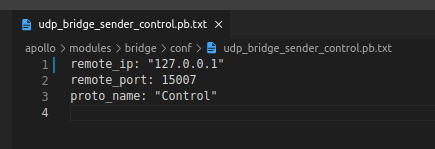
Network settings
The target network the Apollo system will connect to is defined under the bridge configuration directory at apollo/modules/bridge/conf/udp_bridge_sender_control.pb.txt
The remote_ip is the IP address of the machine running MORAI SIM: Drive, and is by default set to 127.0.0.1. This IP address value should be set to match the Host IP address, which should have been set while setting up the simulator network.
Adding MORAI map data
Add the following zip file of map data under this directory: apollo/modules/map/data and extract it. Form the file directory structure as follows: apollo/modules/map/data/[map name]/[map files]
Adding MORAI vehicle data
Extract the following vehicle data zip file at apollo/modules/calibration/data
Building Apollo
Run the shell script command below to finally build the Apollo package. If everything is set up correctly, the terminal should show a Done building apollo. Enjoy! message.
./apollo.sh build_opt_gpu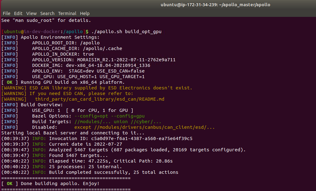
Running Apollo with MORAI SIM: Drive
Now that everything has been set up and configured, we can start Apollo.
Run the bridge launch file to connect Apollo to the simulator.
cyber_launch start modules/bridge/launch/morai_bridge.launchMonitoring performance with cyber_monitor
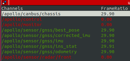
Use the cyber_monitor command to start a status monitor that tracks the different data channels sent to/from the target, which in this case is MORAI SIM: Drive. Refer to this link for detailed instructions on how to use cyber_monitor.
Open a new terminal and type the following script to enter the Docker.
./docker/scripts/dev_into.shOnce completed, run cyber_monitor.
cyber_monitorQuickly check the bridge is working by the color of each of the channels. Green indicates data is flowing between Apollo and the target system. Also, check if the FrameRatio value matches that of the Frame Rate set in the simulator. The cyber_monitor screen should resemble the following screenshot.
Starting Dreamview
Apollo’s Dreamview provides a web-based user interface that allows users to enable or disable different modules within Apollo and to set destinations to navigate to.
Open a new terminal and once again, use the following script to enter the Docker.
./docker/scripts/dev_into.shOnce the Docker is loaded, run Dreamview.
./scripts/bootstrap.shSetting up Dreamview
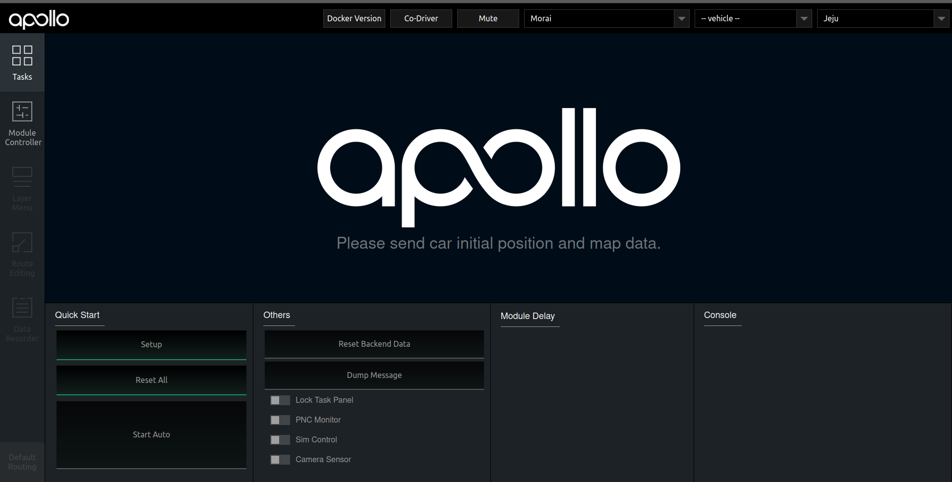
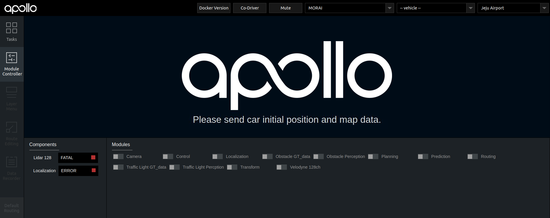
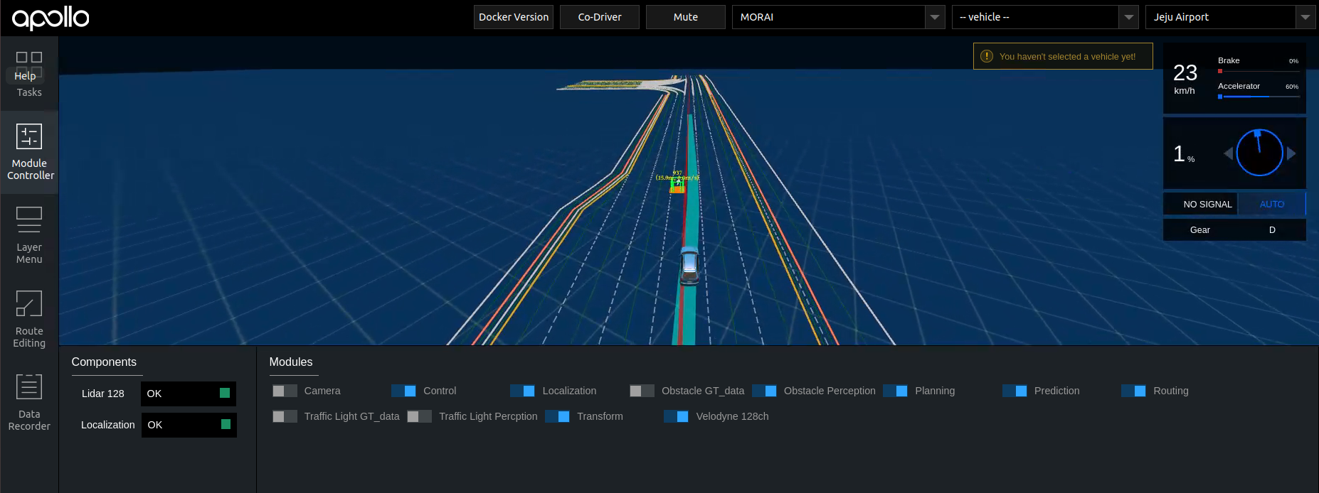
After successfully starting Dreamview, use a web browser of your choice, and type localhost:8888 into the address bar. The following screen should show.
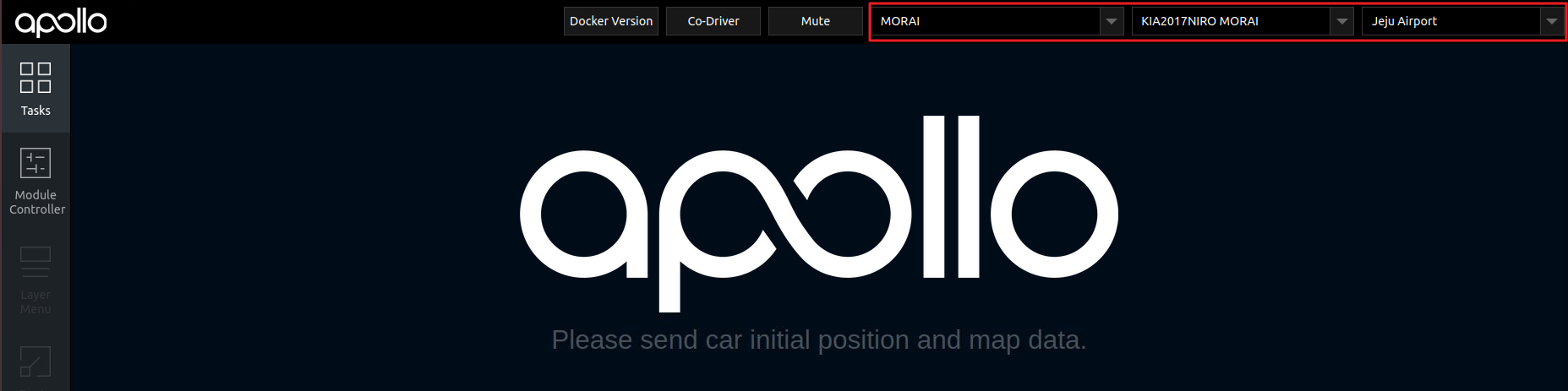
The upper right corner has three drop-down menus where users can select the target system, the target vehicle, and the target map. Set these targets to match the vehicle and map configuration as shown below.
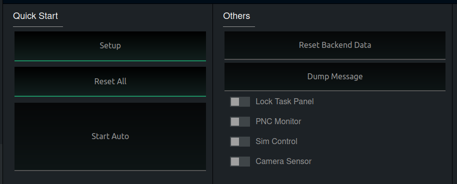
In the Quick Start menu tab located in the bottom-left, click Setup to lock in the vehicle and map configuration.
Click the Module Controller tab on the left-hand side to bring up the Modules panel. We now need to start all of Apollo’s subsystems. Turn on and initialize each module by clicking the toggle switches, and enable all the following functions: Control Localization Obstacle GT_data Planning Prediction Routing Traffic Light GT_data Transform.
If successful, each of the toggled functions will turn blue, and the main screen will load a map, vehicle model, as well as a vehicle status screen.
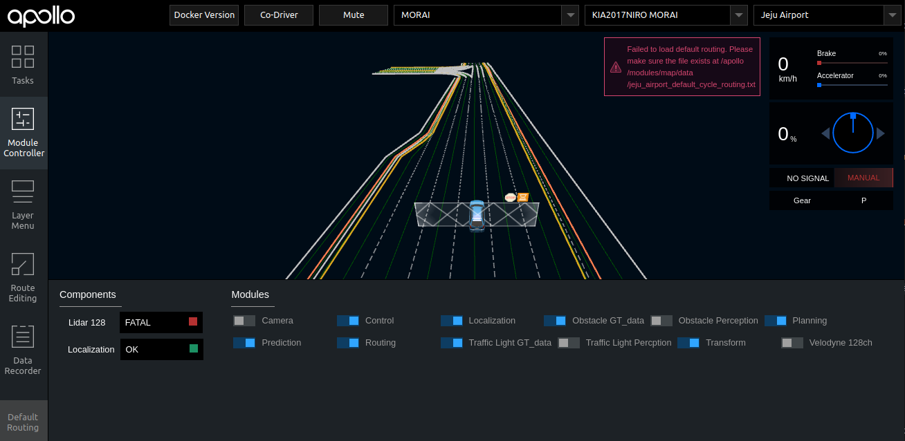
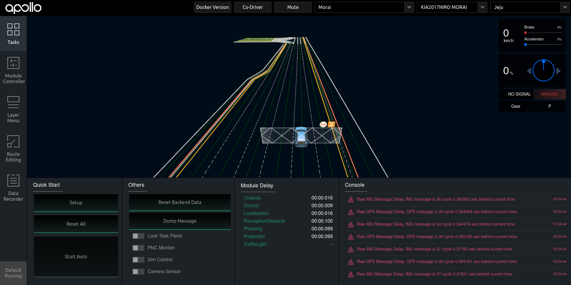
Once everything starts working, the final check is to confirm RTK localization is running by checking the Console log. Once confirmed, move on to the Route Editing tab, which should be the fourth menu on the left-hand menu bar.
NOTE For more advanced applications using the sensor modules, refer to the Advanced steps chapter on performing obstacle detection below.
Building a route and driving through the simulation scene with Apollo
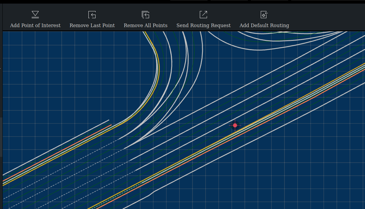
Select Route Editing to bring up a new route planning screen, which is a bird’s-eye 2D view of the map. Compare with the following screenshot.
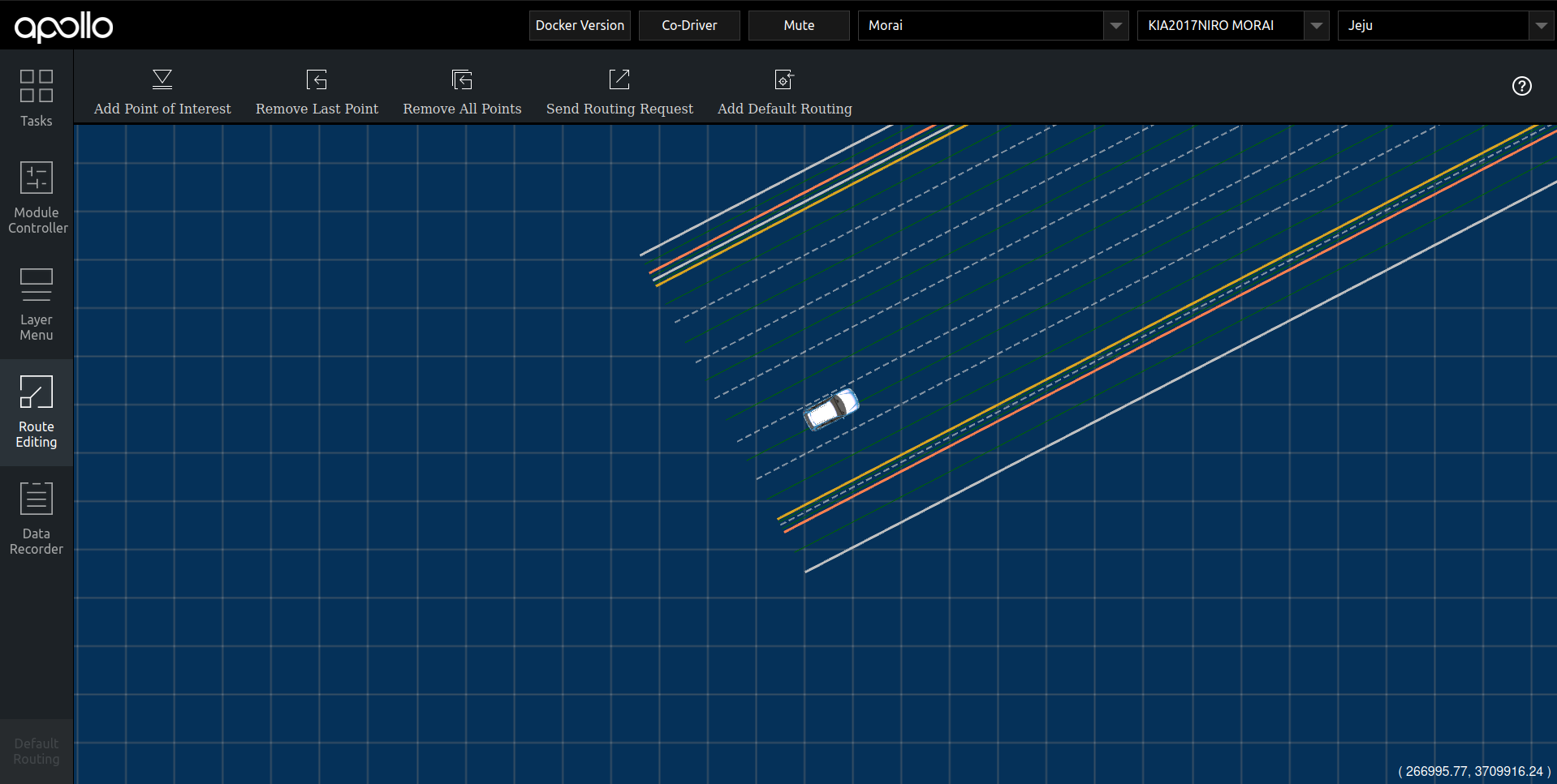
To control the viewport, scroll the mouse wheel to zoom in and out, click and drag the middle mouse button to move, and left-click on a drivable area to set a destination point.
If the destination point is valid, a red dot with crosshairs should appear on the map, as shown below.
To start navigating to this destination point, press Send Routing Request, which should be one of the buttons along the toolbar.
Go back to the Tasks panel, and a path to the destination point should be drawn on the main screen.
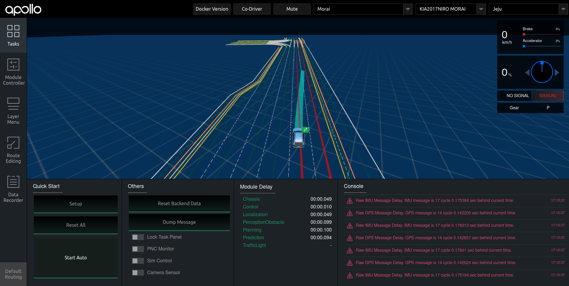
Nothing should be moving as the vehicle in MORAI SIM: Drive is still set to Park. Return the ego-vehicle to Drive mode (press the number 1), then press the Q button to engage Auto-mode. The ego-vehicle should now be connected to Apollo and will start driving along the set path.
Check both Dreamview and MORAI SIM: Drive to confirm if the ego-vehicle is moving. Apollo is providing the control commands to the ego-vehicle, and MORAI SIM: Drive is updating the vehicle’s status variables and broadcasting these changes back to the Apollo system.
Video demo
Advanced steps: Setting up sensors for obstacle detection
Setting up a 128-channel lidar sensor model
Follow the steps for adding sensor models with MORAI SIM: Drive’s Sensor Editor Mode here to add a 128ch lidar sensor to the ego-vehicle. As of version 22.R2.1, the only built-in sensor model with 128 channels is the Velodyne model.
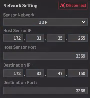
Once the lidar model is placed in the desired position, configure the lidar model’s network settings as follows.
Host Sensor IP/Destination IP: the IP address should match the addresses used for MORAI SIM: Drive’s network settings
Host Sensor Port:
2369Destination Port:
2368
To begin broadcasting to the Apollo system, press Connect at the bottom of the panel.
As a final step, we have to allow the Apollo system to receive lidar data. From Dreamview’s Module Controller tab, toggle on the Velodyne 128ch module.
Screenshot here.
Check lidar sensor output within Apollo
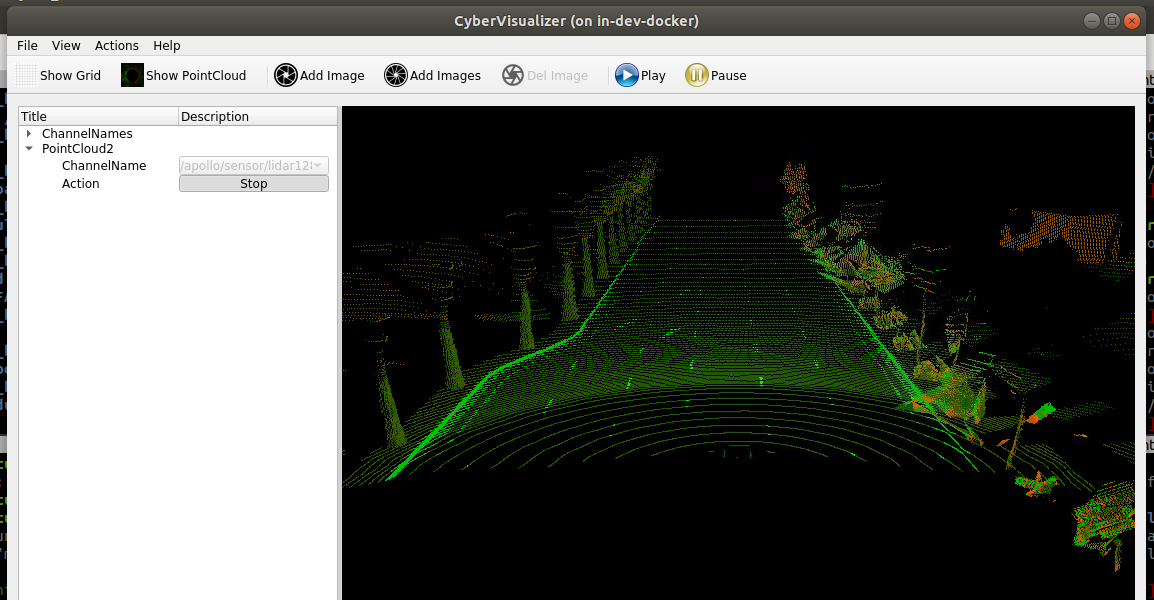
Much like the cyber_monitor feature used to monitor data channels, Apollo has a 3D point cloud visualization tool called cyber_visualizer.
Open a new terminal and type the following script to enter the Docker.
./docker/scripts/dev_into.shOnce completed, run cyber_visualizer.
cyber_visualizerOnce the CyberVisualizer window appears, click the Show PointCloud button located in the toolbar - this should create a new PointCloud2 channel in the data tree window immediately below.
Unfold the tree, then select ChannelName. This should automatically list current lidar channels. Select /apollo/sensor/lidar128/compensator/PointCloud2.
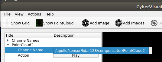
The lidar point cloud will start to show as demonstrated in the screenshot below.
Performing obstacle detection (and avoidance) with lidar
Placing obstacles with MORAI SIM: Drive
Obstacles such as traffic cones and road closure markers can be placed into the simulation scene with MORAI SIM: Drive’s built-in scenario editor.
Use the F2 key shortcut to enter Scenario Edit Mode.
Gif placeholder here.
Refer to the Scenario editor basics page for a deeper dive on placing actors within MORAI SIM: Drive.
Reconfiguring Apollo for lidar-based obstacle detection
In the previous section, Apollo was configured to work without any sensor model input. To reconfigure Apollo to receive obstacle data from its lidar sensors, go to Dreamview’s Module Controller window and turn off the Obstacle GT_data module, and instead turn on the Obstacle Perception module.
Now set a path for the ego-vehicle that runs straight into the user-placed obstacle. Apollo should now adjust its planned trajectory around the perceived obstacle - the light blue path marker should move into another lane. Continue observing the ego-vehicle in both Apollo Dreamview and MORAI SIM: Drive to confirm that the ego successfully maneuvers around the obstacle.
Adding a camera sensor model
Follow the steps for adding sensor models with MORAI SIM: Drive’s Sensor Editor Mode here, this time to add a camera sensor to the ego-vehicle.
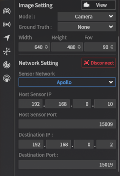
Once the camera model is placed in the desired position, configure the camera model’s network settings as follows.
Host Sensor IP/Destination IP: the IP address should match the addresses used for MORAI SIM: Drive’s network settings
Host Sensor Port:
15009Destination Port:
15019
To begin broadcasting to the Apollo system, press Connect at the bottom of the panel.
Instruct Apollo to begin receiving the camera stream data. From Dreamview’s Module Controller tab, toggle on the Camera module.
WARNING Setting a frame rate value of less than 30 fps within MORAI SIM: Drive may result in a loss of communication.
WARNING A high-resolution camera sensor may cause performance issues depending on your PC specifications.
Checking camera sensor output with Apollo
Unlike lidar sensors, camera sensor output can be checked in two different ways, either directly within Dreamview or using cyber_visualizer.
WARNING Both visualization options cannot be used simultaneously. Turn off the camera view in either Apollo Dreamview or cyber_visualizer to switch between the two.
To turn on the camera view within Dreamview, navigate to the Tasks panel, then toggle the Camera Sensor button located under the Others panel.
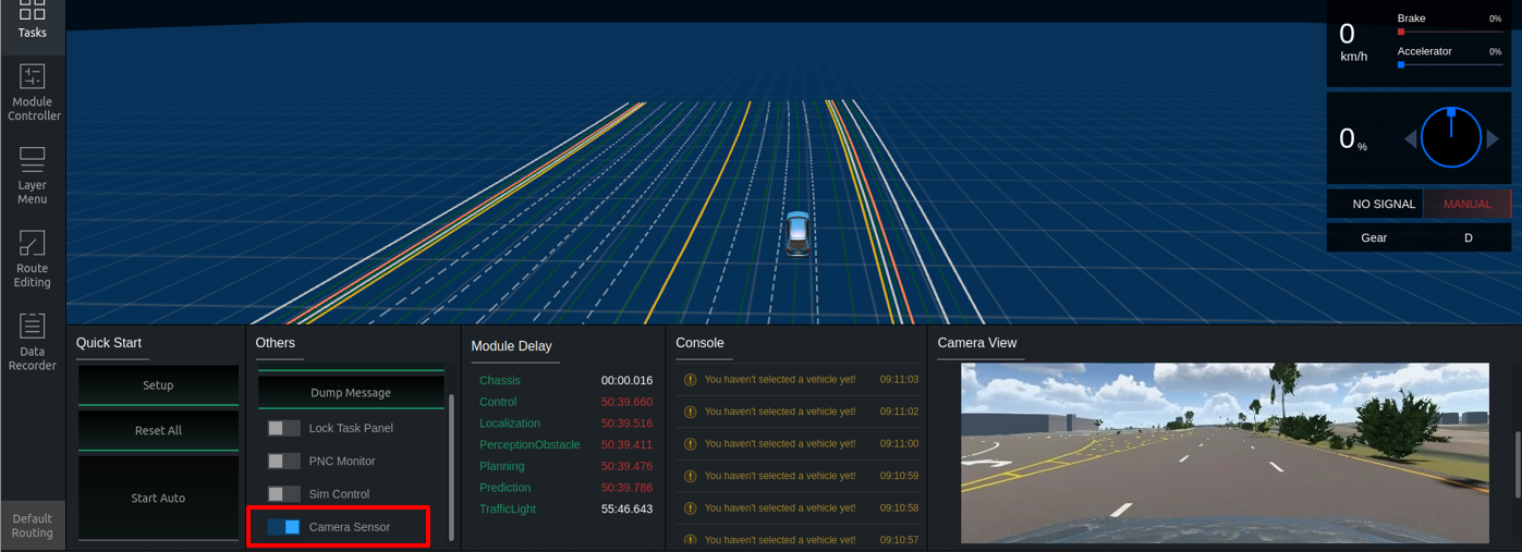
A separate Camera View panel should appear, showing the camera data stream sent from MORAI SIM: Drive.
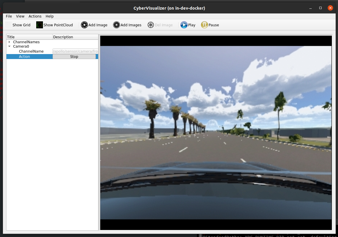
Checking camera sensor output with CyberVisualizer
Using cyber_visualizer requires a separate bridge to run, which we can start by using the following command.
cyber_launch start modules/bridge/launch/morai_bridge_camera.launchOnce completed, run cyber_visualizer.
cyber_visualizerOnce the CyberVisualizer window appears, click the Add Image button located in the toolbar - this should create a new Camera0 channel in the data tree window immediately below.
Unfold the tree, then select ChannelName. This should automatically list current lidar channels. Select /apollo/sensor/camera/front_6mm/image/compressed.
Press the Play button to start streaming the camera sensor’s output

The camera sensor’s image stream should show up as seen in the figure below.
Moving forward
This quick start guide establishes the foundations for using MORAI SIM: Drive with an Apollo autonomous driving system. Users should be able to explore testing different routes and scenarios using a sensor suite of their choosing.
For more maps and vehicle models, as well as access to more advanced features of MORAI SIM: Drive, please contact your account manager or reach out to us.