Sensors
Overview
The Sensor menu allows users to add new sensor models to the scene, change sensor properties, and save/load custom sensor loadouts.
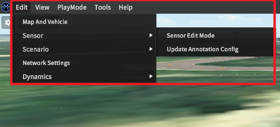
Access the Sensor menu by navigating to Edit >> Sensor >> Sensor Edit Mode through the main menu bar. The simulator window should immediately refocus onto the selected ego-vehicle, and a separate docked window will appear to the side.
Sensor Editor Mode
In editing mode, hold the right-click mouse button while moving the mouse to adjust the view of the target ego-vehicle.
Use the mouse wheel to zoom in (scroll up) and out (scroll down).
Adding and Removing Sensors
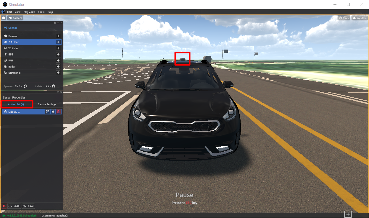
Add sensors to the vehicle by selecting a sensor type from the list of sensor types located in the upper half of the window, then Shift+Left-click on the surface of the vehicle.
The newly added sensor will be the default sensor of the selected sensor type. Sensor models can be changed later in the Sensor Setting window (see the Detailed sensor settings section below).
Any sensor added to the vehicle is added to the Active List within the Sensor Properties window.
To remove a sensor, either:
Click the red delete button from the Active List window (the icon is a trash can).
Alt + Left-click on a sensor located on/within the vehicle’s 3D model.
NOTE Another method of adding a sensor is to load a JSON file with sensor parameters to MORAI SIM. This method allows for the precise placement of all sensors. Refer to the Loading Sensor Configurations section below.
Editing Sensor Settings and Parameters
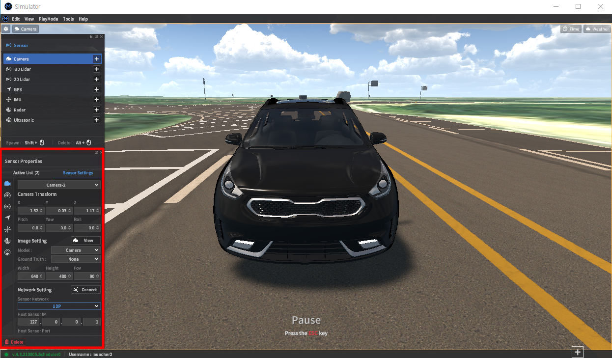
To edit a sensor model, select a sensor type from the Setting Setting tab within the Sensor Properties window. Sensor types are the icons that line the left side of the Sensor Setting tab - if the icons aren’t immediately identifiable, the Sensor list should be used as a quick reference.
Once a tab is selected, the first sensor model of the same type will be displayed by default. Use the drop-down at the top of the tab to switch between different sensors.
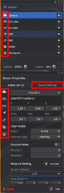
Configurable parameters include sensor position, rotation, sensor type, and sensor connection properties. Details on these parameters continue in the Detailed Sensor Parameters section below.
Detailed Sensor Parameters
Camera sensors
Camera parameters
Position (x, y, z coordinates in meters)
Rotation (roll, pitch, yaw angles in degrees)
Image resolution (by pixels)
Field of view (in degrees)
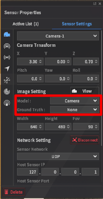
Model type
Camera: selects the standard RGB camera model
Fish Eye Camera: selects a camera with fisheye distortion applied
Physical Camera: allows for adjusting camera parameters such as focal length, and sensor size (see below for a list of options)
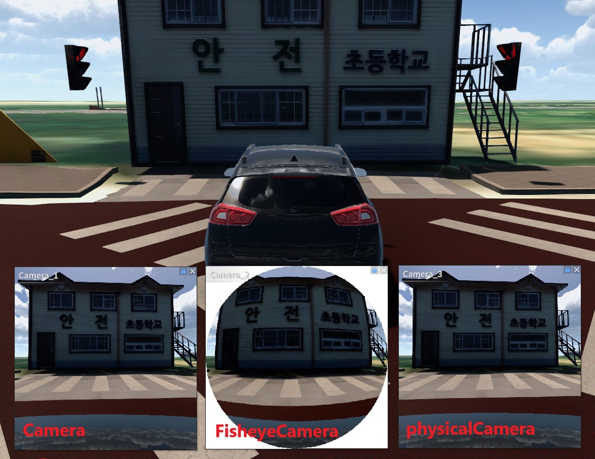
Ground truth options
None: standard RGB output
Semantic: objects are colored according to type
Instance: objects are colored by object instance
Physical camera parameters ADD-ON SERVICE
Intrinsic
Focal length (pixels): distance between the image sensor and the lens
Principal point: point at which the lens center is normal to the image plane
Physical
Focal length (mm): adjusts the distance between the image sensor and the lens
Sensor size (mm): sets the x, y lengths of the image sensor
Lense shift (% of sensor size): distance from the image sensor’s center
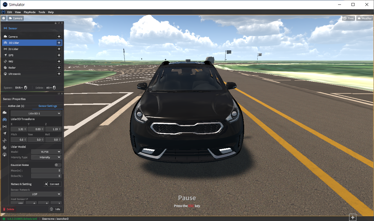
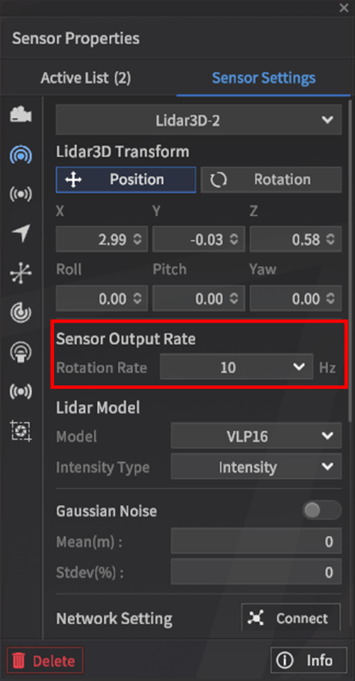
Lidar
Lidar parameters depend heavily on the model of the lidar sensor used. There are around ten different real-world models supported within MORAI SIM: Drive, with the option of adding a customized lidar model.
Position (x, y, z coordinates in meters)
Rotation (roll, pitch, yaw angles in degrees)
Rotation rate (Hz): Determines the data rate at which point cloud data is produced
Lidar sensors' rotation rate cannot be freely set, unlike the data rate options of other sensor models.
NOTE Signal data rate may be affected by machine performance.
Model
Supported lidar models will vary depending on the license version.
Intensity type
Sensor noise
Please refer to the sensor noise settings page for more information.
GPS/GNSS sensors
Position (x, y, z coordinates in meters)
Rotation (roll, pitch, yaw angles in degrees)
Data rate (Hz)
The data rate can be set from 5Hz to 100Hz.
NOTE Data rate may be affected by machine performance.
Sensor noise
Please refer to the sensor noise settings page for more information.

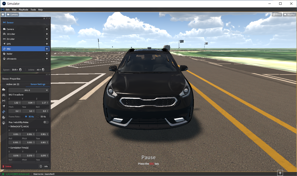
IMU
UPDATE v.4.7 introduces boresight error to the IMU model parameters.
Position (x, y, z coordinates in meters)
Rotation (roll, pitch, yaw angles in degrees)
Data rate (Hz)
The data rate can be set from 5Hz to 100Hz.
NOTE Data rate may be affected by machine performance.
Sensor noise
Please refer to the sensor noise settings page for more information.
Radar
Radar parameters
Position (x, y, z coordinates in meters)
Rotation (roll, pitch, yaw angles in degrees)
Data rate (Hz)
The data rate can be set from 5Hz to 20Hz.
NOTE Data rate may be affected by machine performance.
Viz Radar Range
Toggles an in-client visualization of signal returns detected by the radar sensor models. These returns are shown as yellow point clouds.
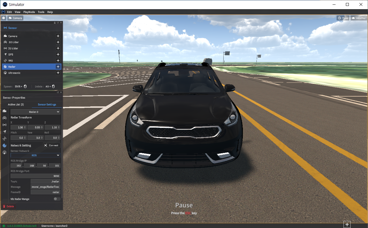
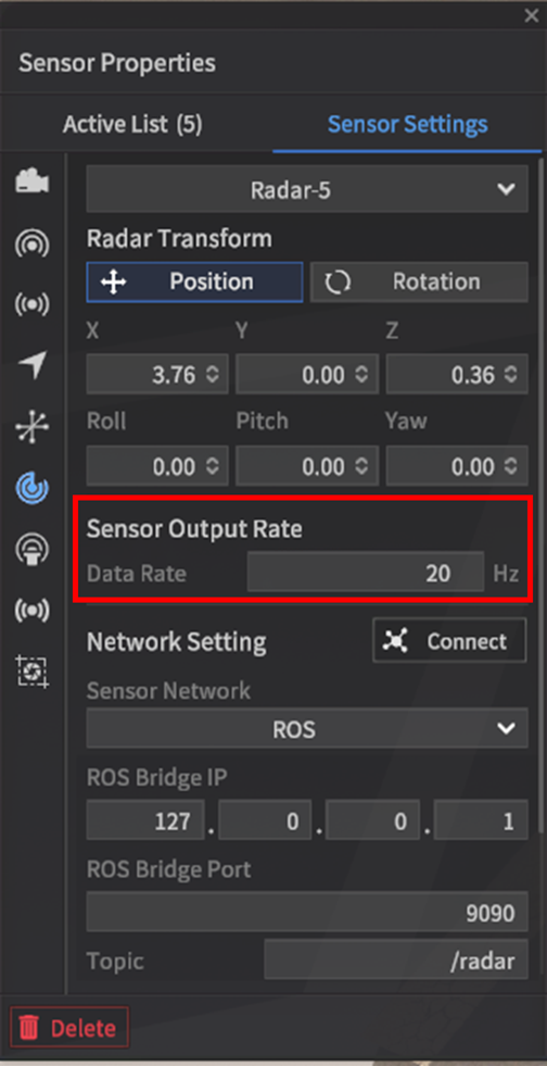
Network Connection Settings
To communicate and relay data to any connected AV/AD software stacks, each sensor can be configured to transmit over ROS or UDP.
ROS
Most of the basics are covered in the Network Settings section of this manual. The specific message types and topic names for sensor data are listed here.
Camera
Message Type: sensor_msgs/CompressedImage
Default Topic: /imag_jpeg/compressed
Lidar
Message Type: sensor_msgs/PointCloud2
GPS
Message Type: morai_msgs/GPSMessage
Default Topic: /gps
IMU
Message Type: sensor_msgs/Imu
Default Topic: /Imu
Radar
Message Type: morai_msgs/RadarDetections
Default Topic: /radar
UDP
For all UDP connections, the simulator requires the user to fill all fields for Host and Destination IP addresses. The basics are covered in the Network Settings section of the manual.
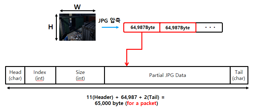
Camera
Image data received by the camera models are compressed into .jpeg format and segmented into 65 kB blocks.
Protocol details
Total packet size: 65,000 bytes
Data field size: 64,987 bytes
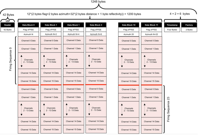
Lidar
The UDP signals from the lidar model can interface directly with ROS drivers provided by the sensor manufacturers. Users of the Velodyne sensor model can use the velodyne package ( http://wiki.ros.org/velodyne ) offered within ROS, while users of other sensors can find relevant drivers and guides online.
WARNING The native ROS settings for lidar models within MORAI SIM may still have issues when simulating lidar sensors with high channel counts.
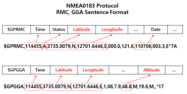
GPS
GPS data is structured in order by Type-Time-Data, and simultaneously transmits RMC, GGA formats of the NMEA0183 protocol.
Protocol details
Type (char)
Time (float)
Data (float) - contains latitude, longitude, and altitude data
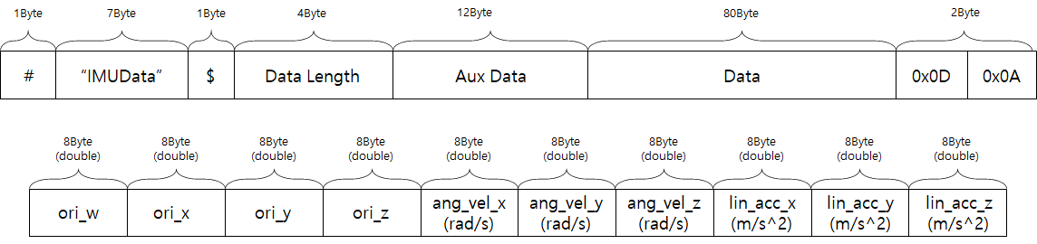
IMU
The IMUData message transmits all of the data produced by the inertial measurement unit.
Protocol details
Total packet size: 107 bytes
Data field size: 80 bytes
Data (double) - packages orientation, angular velocity, linear acceleration values by axis (see packet structure diagram below)
Saving and Loading Sensor Configurations
Access the save and load menus using the dedicated save and load buttons located at the bottom of the sensor configuration window.
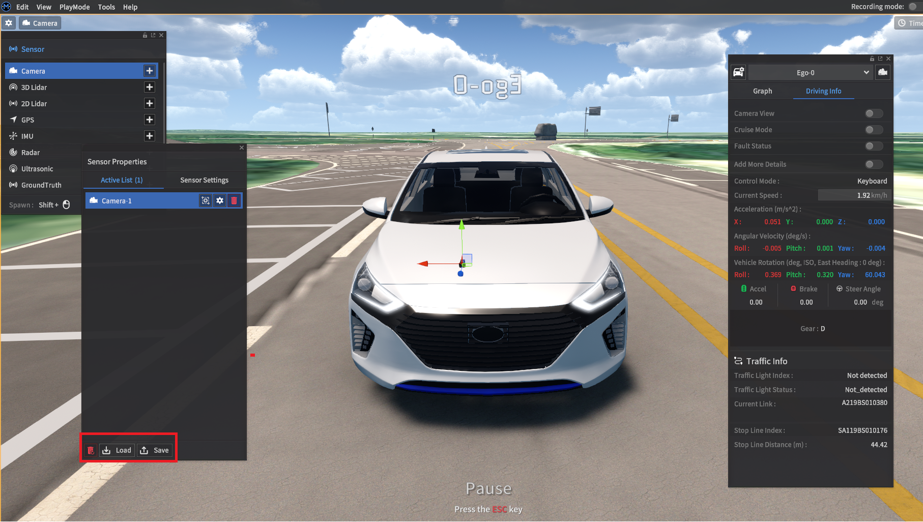
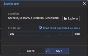
Saving sensor configurations
To save in the default directory, choose a file name and click the Save button. Change the directory by clicking the Explorer button, then navigating to the desired directory.
The default directory is MoraiLauncher_{os}_Data/SaveFile/Sensor/.
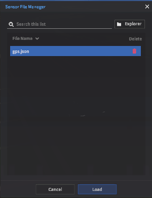
Loading sensor configurations
Select the desired .json configuration from the File List, then click the Load button to the right.
Save files can be deleted using the Delete button in the Sensor File Manager window, or directly through the operating system’s file explorer.