GADC V2X Protocol
Overview
MORAI SIM’s GADC V2X module is configured according to specifications as defined by the Gyeonggi Autonomous Driving Center (GADC). It is divided mainly into V2I and V2V components.
V2I Data
Signal Phase and Timing (SPAT)
SPAT, which represents traffic signal data at road intersections, operates point-to-multipoint between vehicles on the road and a control center. Data is exchanged by request-response.
GADC protocol operates over TCP/IP and is configured as follows:
IP: localhost (127.0.0.1)
Port: 5000
Byte addressing: Little-endian
Request Packet
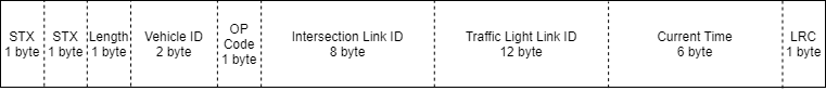
The request packet is a 33-byte signal sent to the control center by the vehicle.
No | Name | Size | Remarks |
|---|---|---|---|
1 | STX | 1 | Fixed at 0x7E, acts as the message header |
2 | STX (repeated) | 1 | Repeats the STX value |
3 | Length | 1 | Total length of the packet excluding the STX fields (i.e. length=0x1F for a request packet) |
4 | Vehicle ID | 2 | Unique identifier for each vehicle - can be chosen freely |
5 | OP Code | 1 | Fixed at 0x12 for request messages (pre-defined by GADC) |
6 | Intersection Link ID | 8 | Unique identifier of the intersection represented as a 8 digit number converted to a string. |
7 | Traffic Light Link ID | 12 | Traffic lights are grouped by direction. ID values are a combination of the intersection link ID and the direction of the lights. Direction code values follow the cardinal directions Intersection Link ID + reserved space (nine “0”s) + Traffic Light ID |
8 | Current Time | 6 | The current time formatted by YYMMDDhhmmss |
9 | LRC | 1 | Acts as the packet checksum, sequentially runs fields 3-8 over an XOR operator |
Response Packet
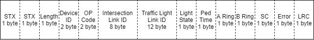
The response packet is a 34-byte signal sent back to the vehicle from the control center.
No | Name | Size | Remarks |
|---|---|---|---|
1 | STX | 1 | Fixed at 0x7E, acts as the message header |
2 | STX (repeated) | 1 | Repeats the STX value |
3 | Length | 1 | Total length of the packet excluding the STX fields (i.e. length=0x20 for a response packet) |
4 | Device ID | 2 | Device ID of the control server - fixed to 0x0014 |
5 | OP Code | 2 | Fixed at 0x13 for response messages (pre-defined by GADC) |
6 | Intersection Link ID | 8 | Follows the Intersection Link ID format of the request packet |
7 | Traffic Light Link ID | 12 | Follows the Traffic Light Link ID format of the request packet |
8 | Light State | 1 | Shows the current traffic light state |
9 | Ped Time | 1 | Time remaining for the pedestrian light signal |
10 | A Ring | 1 | Valid for traffic light controllers using a double-ring sequence |
11 | B Ring | 1 | |
12 | SC | 1 | SC indicates when intersections are in a special control state |
13 | Error | 1 | The error field activates when a malfunction is detected |
14 | LRC | 1 | Acts as the packet checksum, sequentially runs fields 3-13 over an XOR operator |
V2V Data
Basic Safety Message (BSM)
BSM operates via multi-point communication between vehicles. Data is transmitted by broadcast. Protocols are designed according to the SAE J2735 standard.
BSM operates over UDP and is configured as follows:
IP: localhost (127.0.0.1)
Port: 5641 (increases by one for each additional ego-vehicle)
Byte addressing: Little-Endian
Communication Sequence
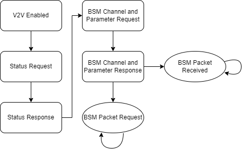
Initial Communication (Handshake)
The PC must send a status request to the terminal at least once to initialize communications.
The equipment communicates only with the socket that sent the status check request and ignores other sockets.
For more details on packet transmission and receival, refer to pages 6 to 8 of the attached BSM specifications document.
We recommend that BSM channels be set to the default channel 172.
BSM Communication
MORAI SIM broadcasts BSM data at a frequency of 2Hz.
Once communications are initialized, all neighboring NPC vehicles begin transmitting BSM data.
For more details on BSM transmission, refer to pages 10 to 13 of the attached BSM specifications document.
경기자율주행센터_V2X_03_WAVE Interface.pdf