Sensor coordinate system
Different sensors also follow their own respective coordinate systems. This page contains summaries of the coordinate systems used in typical IMU, GPS, and lidar sensors.
IMU Coordinate Systems
Measures acceleration, rotational velocity, and orientation across three axes.
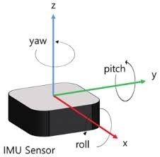
IMU Sensor Output Data
linear_acceleration
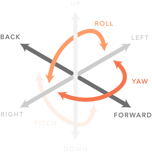
x: Acceleration with respect to IMU Sensor X-axis (Forward +, Backwards -)
y: Acceleration with respect to IMU Sensor Y-axis (Left +, Right -)
z: Acceleration with respect to IMU Sensor Z-axis (Up +, Down -)
angular_velocity
x: Angular velocity with respect to IMU Sensor X-axis (Roll)
y: Angular velocity with respect to IMU Sensor Y-axis (Pitch)
z: Angular velocity with respect to IMU Sensor Z-axis (Yaw)
(sign convention: Counter-clockwise +, Clockwise -)
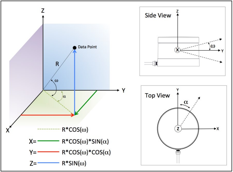
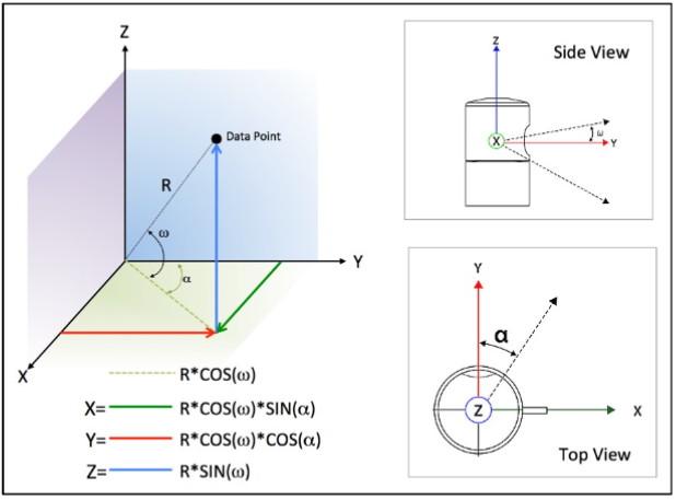
orientation
x: Quaternion X vector
y: Quaternion Y vector
z: Quaternion Z vector
w: Quaternion W vector
GPS Coordinate Systems
Geospatial coordinate reference systems are indicated in each map’s data as a proj4 string.
Each map is based on the specific projection used during the initial collection of map data. Typically real-world-based maps included in MORAI SIM follow the Universal Transverse Mercator (UTM) coordinate system. An example of a CRS for a map based in S. Korea is as follows.
CRS: UTM52N (WGS84) (also EPSG:32652)
proj4 string: +proj=utm +zone=52 +ellps=WGS84 +datum=WGS84 +units=m +no_defs
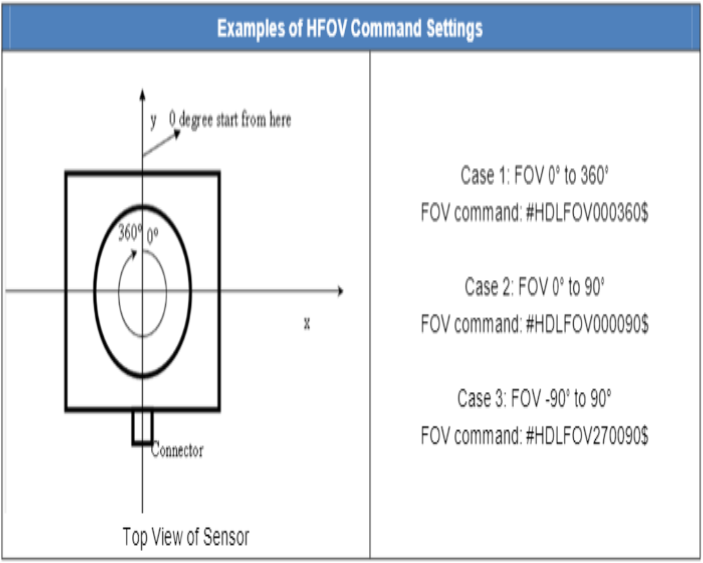
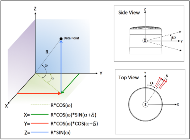
Lidar Coordinate Systems
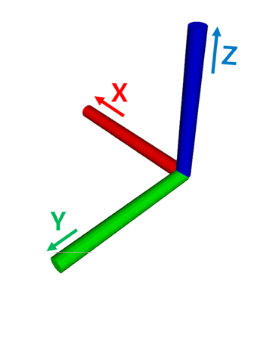
Velodyne Lidars
Velodyne lidar systems follow the convention described below:
x right
y forward
z up
< 16ch LiDAR >
< 32ch LiDAR >
< 64ch LiDAR >
< 128ch LiDAR >
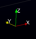
ROS Coordinate System
Information on basic units can be found on ROS Standard Units in ROE 103 (ROS Enhancement Proposals - https://www.ros.org/reps/rep-0103.html#id14)
The ROS coordinate system switches the x and y-axis definitions used in Velodyne lidars
x forward
y left
z up
ROS velodyne_driver
When receiving data using ROS’s velodyne_driver, the ROS standard coordinate system is used instead of the existing Velodyne coordinate system.
Comparison between Veloview and ROS Rviz using MORAI SIM
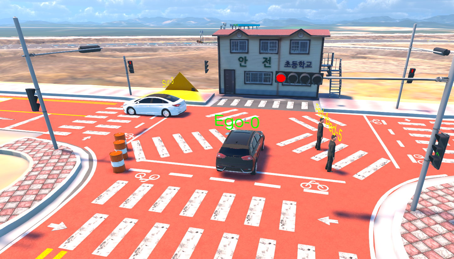
Simulator
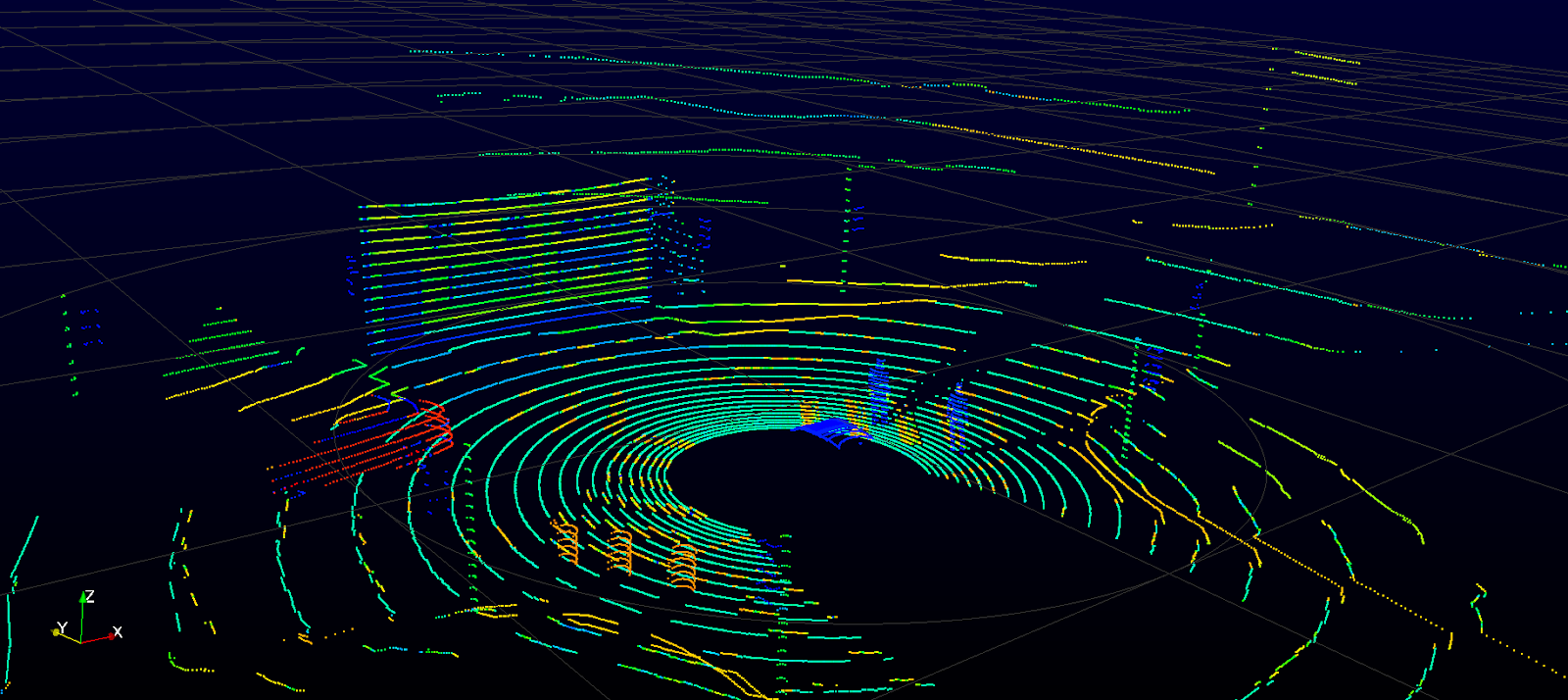
Veloview
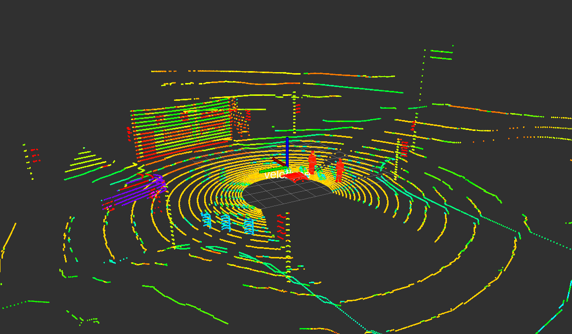
Rviz
Veloview CRS Axis
Rviz CRS Axis